Solid state transistor is ubiquitous in modern life since the 1950's when its usefulness was discovered at Bell Labs in 1947. As shown in Figure 13-03c(a), this device consists of all the three types of solid in the Band Theory. The semiconductor is usually a piece of doped silicon, which allows some free electrons (N-type) or holes (P-type) to move around. The transistor is off admitting
 |
at most a weak current before a certain threshold gate voltage VG (usually a few volts) is attained at the base. Once the gate voltage is over the threshold voltage VTH, the transistor is turned on (acting as a switch) and the current increases exponentially (acting as an amplifier, see Figure 13-03c(b)). Figure 13-03c(c) shows the effect of VG on the valence and conduction bands. The |
Figure 13-03c Transistor [view large image] |
bendings of those are ultimately responsible for turning on the current flow in the transistor when VG - VTH > 0. |
 |
This type is called Field-Effect Transistor (FET) and uses mostly in integrated circuits (IC). There are other types of transistor such as bipolar junction transistor (BJT). It is especially useful as amplifier in analog circuits (see Figures 13-03c2, 13-03e, and "Difference between BJT and FET"). |
Figure 13-03c2 BJT/FET |
 |
 |
|
Figure 13-03d Electronic Circuit |
Figure 13-03e Logic Gate |
- Other electronic components include :
- Capacitor - Filtering and frequency modulation, etc.;
- Triode -Amplifying, switching, etc.;
- Crystal Oscillator - Providing square wave or sine wave;
- Transformer - Changing the voltage;
- Connectors - Connecting two active components to carry the current or signal, etc.
 |
(see Figure 13-03f), and also thank to the limitation of human sight and hearing. The ability to distinguish two very close points is about 0.01 cm, and the perception of image persists for about 1/16th of a second (Due to this, when many still images are shown in a |
Figure 13-03f Digital Age |
sequence; they give the illusion of moving images. For example, when separate images are moved in front of the eyes at the speed of at least 16 frames per second, we experience the images being real and live). The following example is mostly about visual image. |
- Size Scale of the Integrated Chip (IC) - The smallest addressable unit (by software) is a pixel with linear dimension ~ 3x10⁻² cm including spacing (Figure 13-03g). Each pixel is made of 3 sub-pixels, for Red, Blue and Green colors in 1 byte length (= 8 bits) each. The binary value in each byte corresponds to the intensity of the color, for example, "11111111" represents full load while "00000000" indicates its absence. In this case, there would be 28 = 256 different shades of colors. As it will be explained later, ultimately the shade is determined by the gate voltage VG to a transistor (see Figure 13-03c).


Figure 13-03h zooms into the IC to show its innards in size scale ~ 100 times smaller on each successive frame :
(a) IC in package with linear dimension ~ 5 cm.
(b) Interconnecting tracks under the IC with size ~ 10-2 cm.
(c) Further enlargement of the tracks ~ 10-4 cm.
(d) An image of the transistor ~ 10-6 cm.Figure 13-03g Pixels
[view large image]Figure 13-03h Size Scale of IC [view large image]
[2024 Update] : - Image Scanning - The pre-digital era used to capture image on film which has three layers of emulsion, each layer is sensitive to a different color, it records on each tiny spot of the film to reproduce the same color as the image projected onto it, same as the lens perceives and the human sees. The following uses the modern version of the camera to illustrate how it is done in digital age. Essentially, it converts the analog image to binary numbers. Instead of using the film to keep the image, it stores the digitalized image on a digital file. The image is retrieved by more electronics to display it again digitally in such a way that we consider it to be as good as the original. The various panels (from "a" to "d") in Figure 13-03i explain in some details about such modern process (see "A few scanning tips").
(a) This is a high level view of the process. It uses a mosaic filter to capture the colors of the image. The basic element is the pixel (or photosite in camcorder's lingo) as described earlier or a variation (called Bayer pattern with 2 green sub-pixels). This pattern is transformed to digital file by the analogue/digital converter (ADC).
For video scanning, the photosites reset to start the exposure to the next frame after the conversion is complete.
(b) This one shows the 2 different designs of the image scanning systems - CCD (Charge Coupled Device) and CMOS (Complementary Metal Oxide Semiconductor) image sensors. While CCD goes through the photon-to-electron (involving the capacitor C) and electron-to-voltage (as the amplifier A, both C and A are FET) steps within the image sensor before running the ADC process in an circuit board, the CMOS has these steps completed in the pixel and the ADC is executed within the image sensor (see further information in "Background Information on CCD and CMOS Technology").
(c) Further elaboration on CCD and CMOS, especially on the charge transfer step in CCD in which the electrons are moved from one register (pixel) to another serially.Figure 13-03i Image Scanning
[view large image](d) This is a pictorial displays about photon-to-electron in the FET, and electron transfer by shifting the applying voltage (to the FET) in CCD.
- Storage - DVD (Digital Video Disc) appeared in the market near the end of last century allowing up to 17 GB of storage and gradually replacing the analogue cassette tapes invented back in the 1960's. The capacity of DVD has improved over the years up to 128 GB in Blu-ray format (Figure 13-03j). The decline of DVD technology is not so much about capacity as
(a) Compact Discs has gone through many incarnations from CD to DVD, HD-DVD, and now Blu-ray. As shown in
Blu-ray disc has enough space to keep so many copies of movie; it is the advant of broadband internet streaming (also see "List of streaming media services"), which skips the requirement of storage as opposite to downloading. Anyway, the Blu-ray and its like are still somewhat useful today (as of 2022) for keeping a copy of whatever. However, the USB (thumb drive) is a preferable alternate. Since the mid 2010's, the laptop computers Figure 13-03j Digital Storages [view large image]
and audio port in automobiles have the DVD slots replaced by USB terminals.
Followings are brief description of the digital elements in various storage media.
Figure 13-03k,a, the size of encoding element (in a piece of aluminum) decreases, and hence both the data density and capacity increase (from 0.7 GB) in each succession.
CDs are made from an original "master" disc. The master is "burned" with a laser beam that etches bumps (called pits) into the aluminum surface. A burned bump represents the number zero. The reflective spot is the unburned area (called land) representing the binary number 1. Thus, the laser can engrave all the information sampled from the original track of music or image in series of 0's and 1's on that thin piece of aluminum. In the read-back process (see Figure 13-03k,b, the laser (moving in and out from the center) flashes up onto the shiny (under) side of the CD, bouncing off the pattern of pits (bumps) and lands (flat areas) on the disc. The lands reflect the laser light straight back, while the pits scatter the light.
Every time the light reflects back, the attached photocell detects it, realizes it has seen a land, and sends a burst of electric current to an electronic circuit that generates the number one; otherwise, the electronic circuit generates the number zero. The series of data on the disc is decoded by an electronic circuit (called digital to analog converter or Figure 13-03k Compact Discs [view large image]
DAC) in the CD player and converts them back into a changing pattern of electric currents. A loudspeaker transforms the electric currents into sounds (by changing their electrical energy into sound energy).

(b) As shown in Figure 13-03l, the Hard Disk Drive (HDD) Read/Write (R/W) mechanism is similar to those employed for Compact Disc (CD), except that the binary numbers are represented by magnetized spots on the disk. A typical HDD consists of a spindle that holds the platter. The platter is made from a non-magnetic material, usually aluminum alloy, glass, or ceramic. It is coated with a shallow layer of magnetic material typically 10-20 nm in depth, on which the digital data are magnetized with opposite magnetic field direction (related to the pre-set field) as 1 and otherwise as 0 (see Figure 13-03m,b). [view large image]
Figure 13-03l HDD R/W
(c) The USB flash drive (available since 2010) is a data storage device using flash memory (see "How USB Flash Drive Work?") to store data with an integrated USB interface (see Figure 13-03m). It is typically re-movable, re-writable and much smaller than an optical disc. The flash memory is similar to the Field Effect Transistor (FET, see Figure 13-03c,a), except that the insulator under the "Gate (now called Control Gate)" is replaced by the "Floating Gate" which stores electrons by applying voltage to the "Control Gate' creating the binary number 1 ("0" is represented by no charge). The charges can be removed by applying high voltage to the source (see Figure 13-03m and Figure 13-03n,c). Figure 13-03m USB Flash Drive [view large image]

(d) Solid-State Drive (SSD) uses flash memory similar to the USB flash drive. As such, it has no moving parts unlike the HDD and its storage capacity can surpass the HDD too (Figure 13-03j). See "What Is a Solid-State Drive (SSD)?" for further detail. Figure 13-03n Storage Element [view large image]
- Reception of signal involves transmission from the sender and a device for its retrieval (see Figure 13-03f,c). Lot of progresses have been made for both aspects in the 21st century. here's a brief introduction mostly about how they work.
(a) The concept of broadband internet depends heavily on frequency modulation for speedy delivery of data (aka signal, information, ...). Figure 13-03o shows a very simple example of frequency modulation with a single channel at low frequency. The whole idea is captured by the formula :

where Am = amplitude of the message wave (in blue color, under subscript m), fm = message frequency, m = 2
m = 2 fm, fc = carrier frequency, c = 2fc, modulation index
  =
=  f/fm, f the frequency deviation (from fm), and bandwidth = 2(f+fm).
Note 1 : The abscissa in Figure 13-03o, diagram (a) denotes time t in unit of second and represented by Eq.(1), diagram (b) is in unit of frequency f (Hz = # of oscillations per sec) and diagram (c) is in unit of number of side-bands.
Note 2 : The modulation of the carrier frequency is via the last term in Eq.(1). It appers as a time varying (in sine wave form) phase change to modify the carrier frequency fc which is usually much higher than fm.
Note 3 : It is the side-bands which deliver the messages. The carrier wave is suppressed in "Reduced-carrier transmission".
Note 4 : The side-band amplitude depends onf as shown in the table below left :
Note 5 : Binary data of 0 / 1 are encoded as slightly higher and lower frequencies in the side-bands, see graph below right :

By 2022, viewing of video is no longer a very slow process by downloading with a modem. Now the broadcast comes on

the screen instantly without delay, thank to the 19th century technique called "multiplexing" (more precisely "frequency multiplexing in this case) which is known now as "broadband internet". As shown in Figures 13-03p and 13-03q, the data are separated into several packages (called channels) near the carrier frequency. The information bearing wave would have certain bandwidth after modulation (see Figure 13-03o). These "data waves" would travel different routes in parallel Figure 13-03o
 Frequency Modulation
 Figure 13-03p Broadband Internet [view large image]
making the delivering time much shorter. They are finally reassembled at the receiving end to be viewed. 
In practice, There are 2 carrier frequencies of 2.4 and 5 GHz in use by the public. The 2.4 GHz has 14 channels for bandwidth of either 20, 40, or 80 MHz (Figure 13-03r). Use of the 5 GHz with bandwidth up to 160 MHz may encounter problem with channel interference as the separation between them is reduced by about 1/2 (as compared to the 2.4 GHz), although data transfer rate would improved as it depends on bandwidth, i.e., broader bandwidth (hence "broadband") packs more data. Figure 13-03q [view large image]
Broadband Transmission
Overlapping affects 2.4 GHz as well; therefore, only channels 1, 6, 11 are typically used in the US. In the rest of the world, the four channels 1, 5, 9, 13 are typically recommended (see "Wireless Radio Channels", and "2.4 GHz Channel Planning"). Figure 13-03r explains the concepts of carrier frequency, distribution of channels (and the overlappings), and bandwidth. Figure 13-03r
Frequency Channels The insert at upper right corner is an one channel packet with signal near the carrier frequency fc , the Side-Band (SB) within the Band-Width (BW) can also deliver data . Each carrier frequency is modulated as shown in Figure 13-03o.
Followings are brief descriptions (with references) on some special terminologies in the cyberspace for the novices :
Speed of the broadband internet depends on bandwidth (to pack data) as well as number of channels (for dividing data into packets in transmission and reassembling them at the receiving end). The example in Figure 13-03r has bandwidth of 22 MHz, which would be advertised in the trade as 20 Mbps Max with bps standing for "bits per second" or bits/sec.
Common mediums of transmission include fiber (see "Optic Fiber"), wireless, satellite, digital subscriber line (DSL), cable modem, and broadband over power lines (BPL).
Mobile broadband receives the data package directly from radio transmission (actually via the various plans offered by Internet Providers, see "Cell Phone Plans"). Similar service is also available via fiber cable connection (Figure 13-03s,a). These services are provided only in big cities where cost-profit margin is favorable for installing the fiber network.
See the latest 5G networks for Mobile Broadband.
WiFi Hotspot is free WiFi service (with or without a password, but with no security) offered to the public by stores, offices, ... via a router.

Digital Subscriber Line (DSL) also provides fast data transmission over copper telephone lines (instead of the even faster fiber cable). The "A" in ADSL refers to "Asymmetric" between more downloads than uploads (Figure 13-03s,b).
Figure 13-03s
Internet ServiceDialup internet use 20th century technology with modems to convert data from digital to analog and back to digital at the sending and receiving ends of a telephone line respectively. It is now used mostly in rural areas.
Media Access Control address (MAC address) is a hardware identifier that uniquely identifies each device on a network. Primarily, the manufacturer assigns it. A MAC address can also be referred to as a burned-in address, Ethernet hardware address, hardware address, or physical address.
Meanwhile, an internet service provider (ISP) or network administrator assigns an Internet Protocol address (IP address) to the client. Associated with the TCP/IP protocol, an IP address identifies a device connected to a network. It can be linked to an easy-to-remember domain name (name of the website as known in the street, see Figure 13-03t).

- IP address protections :
- Use a proxy server.
- Use a virtual private network (VPN).
- Use a reliable antivirus software and keep it up to date.
- Stay alert to phishing emails and malicious content.
- Change privacy settings.
- Create unique passwords.
Figure 13-03t
IP Address - Domain Name
(b) Finally, the signals reach the destination. Here's a brief description to explain how they become the image on the screen :
The LCD display relies on a special property of certain Liquid Crytal (LC) to alternate the polarization of light. It is in turns controlled by the on and off of the ultra-tiny transistors. Followings describe the sequence which determine the state of a pixel in the displaying panel (see Figure 13-03u).
For those of us old enough to remember the CRT monitor in the 20th century. It was a chunky and very heavy object occupying 1/3 of the desk space (look like the image on the left). It was replaced by the plasma monitor in the early 2000's and followed subsequently by the LCD, and now OLED. - The light source is un-polarized from the back of the panel (hence called Backlight).
- The 1st polarizer admits only vertically polarized light to go through.
- In the absence of voltage V, the liquid crystal would rotate the light from vertical to parallel polarization permitting it to go through the 2nd parallel polarizer (see Figure 13-03a,c).
- For V
 0, the liquid crystals are aligned with the field direction, and let the passing light to go through. It is eventually blocked by the 2nd parallel polarizer, the screen becomes dark (Figure 13-03b).
 - The on and off of the voltage is controlled by the TFT (Thin Film Transistor)

Figure 13-03u LCD Display
[view large image]which is in turn controlled by the incoming signal. Figure 13-03d shows a small section of the LCD rectangular array. The RGB filters enables the display of vivid color. - Some organic molecules have partially free electrons (called Delocalized electron) roaming between them. This property makes the system behaving like a semiconductor with some electrons staying in the conduction band.
- Applying an electric potential on this system returns some electrons to the partially filled valence band and emitting a photon in the process. The energy of this photon (i.e., the frequency or color of the emitting light) depends on the energy gap between the 2 bands (see Figure 13-03v,a for a single sub-pixel, diagram b displays a LED pixel).
- The bi-layer design allows different conducting property in 2 zones to provide a more gradual electronic profile (Figure 13-03v,c).

Figure 13-03v OLED Display
[view large image]See "What's So Good About OLED" and the next generation PeLED.
Figure 13-03v,d is reminiscence of the first flat screen technology which uses different kinds of plasma to excite phosphors to emit light.
Now that the chip is getting smaller to the nano-meter scale as shown above; it reaches some physical barriers which requires ingenuity to overcome. ChatGPT has provided a summary below (in Italic text) :
1. Limits of Chip Miniaturization
Smaller chips (below the nanometer scale) face a range of challenges:
" Quantum Tunneling: As transistors shrink, the insulating barriers between them become so thin that electrons can tunnel through, leading to leakage currents and inefficiency.
" Heat Dissipation: Higher clock speeds and greater transistor density mean more heat per unit area, which is difficult to dissipate effectively.
" Signal Integrity: Smaller transistors and interconnects mean higher susceptibility to noise and signal degradation.
________________________________________
2. Approaching Physical Limits
Modern chip designs (like those at 2 nm or smaller) approach the atomic scale, where classical semiconductor physics transitions to quantum effects. This doesn't mean it's impossible to make smaller chips, but:
" New materials (e.g., graphene, 2D materials) and structures (e.g., FinFET, Gate-All-Around transistors) are required.
" Technologies like quantum computing, which uses qubits instead of classical transistors, offer alternatives to traditional chip design.
________________________________________
3. Potential Solutions and Alternatives
" Low-power designs: Innovations like better thermal management, reduced operating voltages, and efficient architectures.
" Parallel computing: Instead of increasing clock speed, chips now rely on multicore designs and parallel processing.
" 3D stacking: Chips can expand vertically, offering higher performance without further miniaturization.
" Post-Moore's Law technologies: Approaches like photonic chips and neuromorphic computing could bypass the limits of traditional silicon.
See "Single Photo (2024)"
 ________________________________________
In summary, while chips are indeed approaching physical and practical limits, continued innovation in materials science, chip architecture, and alternative computing paradigms will drive progress beyond the current barriers. The uncertainty principle isn't a direct limiting factor for heat or size, but quantum effects do become more prominent as chip features shrink.
The most advanced semiconductor chips are being developed by a few leading manufacturers:
1. TSMC (Taiwan Semiconductor Manufacturing Company): TSMC leads the industry, producing over half of the world's semiconductors. It is the only company, alongside Samsung, capable of manufacturing chips using the most advanced 3nm process node, and it is progressing towards 2nm and even 1.6nm-class nodes by 2026. These advancements leverage cutting-edge technologies like nanosheet transistors and backside power delivery for improved energy efficiency and performance
2. Samsung: Based in South Korea, Samsung is TSMC's closest competitor. It also produces 3nm chips and is pushing advancements to compete in high-performance computing and mobile applications
3. Intel: While not as dominant in foundry services, Intel is investing heavily in its advanced node development. Its roadmap aims to regain technological leadership in the next few years by focusing on innovative manufacturing and design technologies
4. GlobalFoundries (A foundry is a factory that produces metal castings) and UMC: While they focus on less advanced nodes compared to TSMC and Samsung, these companies are crucial players for manufacturing in sectors that do not require cutting-edge chips.
These companies are at the forefront of technological innovation, pushing the limits of what is possible with semiconductor fabrication. TSMC and Samsung's dominance is driven by their ability to invest heavily in research and development and maintain advanced production capabilities.
[End of 2024 Update] :
 |
 |
||
Figure 13-03w |
IC Fabrication [view large image] |
- Pre-treatment and Wafer Forming - The most common method for silicon wafer preparation involves preparing a single crystal seed and dipping it into molten silicon. Once in the liquid, the seed is pulled from the molten silicon slowly, while the rod rotates (Figure 13-03x). Then, the finished wafer is polished and has a crystallographically flawless surface. The circumference of the monocrystalline ingot is ground down to a uniform diameter. Then the sliced wafers are polished by alumina abrasive in a lapping machine to the desired thickness, while improving the surface parallelism.
- Cleaning - The purpose of silicon wafer cleaning is to maintain a clean and dry surface. The adhesion between substrate and resist (a resistant substance) is of major importance for the safe processing of photoresists (light-sensitive coating).
- Oxidation - This process creates an SiO2 layer, which serves as an insulating layer that blocks leakage current between circuits. The oxide layer also protects the silicon wafer during the subsequent ion implantation and etching processes.
- Deposition - This is the process to deposit thin films of conducting, isolating or semi-conducting materials (depending on the type of the structure being made) on the wafer to enable printing of the first layer on it. One of the method is Chemical Vapour Deposition (CVD) which deposits material in hotter gas phase onto a cooler surface (see "Explained: chemical vapor deposition", "Virtual Chemical Vapor Deposition Lab", and Figure 13-03y).
- Chemical mechanical polishing/planarization (CMP) - This is a process that removes materials by a combination of chemical and mechanical (or abrasive) actions to achieve highly smooth and planar material surfaces.
- Ion Implant - Ion implantation is a surface treatment process in which ions of nitrogen or carbon are accelerated and made to penetrate the thin film endowing it with wear resistance.
- Photoresist Coating - Photoresist (also known simply as a resist) is a light-sensitive material used in photolithography and photoengraving to form a patterned coating on a surface.
- Lithography - Lithography is the process of transferring patterns of geometric shapes in a mask to a thin layer of radiation-sensitive material (called photoresist) covering the surface of a semiconductor wafer.
- Etch - In semiconductor device fabrication, etching refers to any technology that will selectively remove material from a thin film on a substrate and by this removal create a pattern of that material on the substrate.
- Wafer Probe - A wafer prober is a system used for electrical testing of wafers in the semiconductor development and manufacturing process.
- Packing - This final fabrication process gets the chips out of the wafer, it is sliced and diced with a diamond saw into individual chips. The chips are cut from a 300-mm wafer, the size most often used in semiconductor manufacturing, these so-called 'dies' differ in size for various chips. Some wafers can contain thousands of chips, while others contain just a few dozen. Figure 13-03z2 illustrates why Integrated Chip (IC) becomes a hot topic in this digital age (see "Three months, 700 steps: Why it takes so long to produce a computer chip" by Washington Post, 2021; and "Causes of global chip shortage").
 |
|
Figure 13-03x |
 |
|
Figure 13-03y |
 |
|
Figure 13-03z |
|
 |
|
Figure 13-03z2 |
Here's a YouTube video on "How ASML, TSMC And Intel Dominate The Chip Market". ASML - Advanced Semiconductor Materials Lithography. TSMC - Taiwan Semiconductor Manufacturing Company = 臺積電 |
- Basic Elements - Conventional computers process information by breaking it up into its component bits and operating of those bits a few at a time. These computers consist primarily of electronic circuits including bits, wires, and gates. Bits can be implemented by ferrite cores (in memory), magnetic spots (in hard-disk), or the on and off of the voltages. These bits can be sent along wires to the logic gates for processing. It has been shown that any desired logical expression, including complex mathematical calculations, can be built up out of the OR, AND, and NOT gates (see Figure 13-03z3, and an example using NAND).
 |
|
Figure 13-03z3 Logic Gates |
The same figure also shows the corresponding electronic circuit to implement the logic gate (just one example for the AND gate). Logic gates are primarily implemented using diodes or transistors acting as electronic switches. See "List of Logic Gates". |
 |
The inputs are kept in storages initially far away from the CPU when they are not needed. Those that are required for operation has to be housed in a place called register which can response as quick as the clock cycle (see Figure 13-03z9). |
Figure 13-03z4 Hierarchy of Memory [view large image] |
Here's a summary of the various kinds of storage according to capacity and speed (also related to cost - more expansive for the speedier ones, see Figure 13-03z4). |
- Register - Registers are data holding places as integrated parts of the CPU (see Figure 13-03z4). It is a special kind of

memory providing the quickest input/output of data (to the CPU). Its structure is very simple to hold 8, 16, 32 or 64 bits of binary numbers. It is usually implemented as "Flip-flop and then Latch" by 4 BJTs. Figure 13-03z5 shows a single element holding 1 bit of data which is set to 0 or 1 by a pulse of electric current and then holding it at that state until the next clock cycle for executing another instruction (see Figure 13-03z5).
Figure 13-03z5 [view large image] Processor Register
There are many types of register, each one has a special name in Assembly language (see for example, "Assembly - Registers").
- Cache Memory - It stores a copy of the data/programs which are used very often. The high-speed memory retrieval would improve the performance of the CPU. It has 3 different levels as shown in Figure 13-03z4.

Cache memory is implemented by the Static Random Access Memory (SRAM), which follows the same architecture for register but using 4 FETs instead (see the "difference", and Figure 13-03z6). It helps the processing because of no need for searching the information everywhere (if the information is in there already). Caching can also be applied and leveraged throughout various layers of technology including Networking layers, Content Delivery Networks (CDN), DNS, web applications, and Databases. Figure 13-03z6 Cache
[view large image]Some computer also add buffer (a temporary storage) to queue up data for synchronization with the faster cpu processing.
- Random Access Memory (SRAM/DRAM) - RAM is computer's short-term memory. In the most common form of computer memory, dynamic random access memory (DRAM), a transistor and a capacitor are paired to create a memory cell, which represents a single bit of data. The capacitor holds the bit of information - 0 or 1. The transistor acts as a switch that lets the control circuitry on the memory chip read the capacitor or change its state. However it is volatile, meaning that the contents would disappear once the power is turned off. There are two main kinds -

the Static DAM (SDAM) used for cpu cache needed constant power supply (hence Static) and Dynamic DAM (DRAM) used for fast primary storage needed intermittent power refreshment (hence Dynamic). See "Difference between SRAM and DRAM". The small voltage from the memory cell is bumped up by the Sense Amplifier. Figure 13-03z7
RAM AddressingFigure 13-03z7 shows the addressing and read/write schemes for SDAM and DRAM.
Multiplexing/De-multiplexing refers to break up and then recombine back the whole for expediting the transmission process. Also see "DRAM Read/Write". - Secondary Memory - See Non-Volatile Storages

 |
 |
Figure 13-03z8 CPU Structure, Data Formats [view large image], |
Datapath for R-type (ADD), and I, J Types |
Data memory: Larger grid of memory cells that are used to store main information to be processed by the CPU (for I-type).
 |
Control Unit (CU): It takes in the opcode from the current instruction, and sends signal to the the corresiponding processor. Different signals are generated on each clock cycle to make the overall operation happen. Figure 13-03za links all kinds of CU opcodes to various processors. While Figure 13-03zb lists the values of different CU opcode for various operations (the JtoPC = branch, X = ignored, ALUcontrol is not opcode - it is added to show its relationship with the ALUOp). |
Figure 13-03z8a Control Unit (CU) Signals for ADD [view large image] (Figure 13-03z8b)
| 
|
- Clock Cycle -
- It is possible to build a CPU with continous supply of electrical energy provided there is a mechanism to ensure each step has all the ingredients (from the previous step) to run the processing. This is called asynchronous operation, which requires lot of efforts to maintain. For each subsequent step, the data will not be ready if starting too soon, while the required information would disappear if waiting for too long (see Figure 13-03z9,c).
- In CPU running with synchronous pulses of electrical energy (1 pulse = 1 clock cycle), the processing of each step has to complete during the interval set by the "machine cycle = n clock cycles" (n
 1). Some cycle may have some free time since the temporal requirement would be different for each step and the machine cycle has to be the longest to accommodate all steps (hence the base for "Instruction Pipelining"). Such processing is automatic and doesn't need extra efforts to supervise (see Figure 13-03z9,a and b which also show the Instruction Cycle = N machine cycles for N 1 from beginning to end of an instruction).
 - The clock cycle is generated by piezoelectric crystal such as the quartz which behaves like the RLC circuit with less energy loss and very stable. The period can be 10-6 to 10-9 sec depending on CPU model.

Figure 13-03z9 Clock Cycle
[view large image]
 |
 |
Figure 13-03z11 shows the clock cycles consumed in the process and reveals that very little time spends on the bus (omnibus in Latin), It is the retrieval which takes up most of the time - 2 cycles in this example, while there could be more. Meanwhile, this step also increases the Program Counter (PC) by 4 bytes using the ADD instruction to point to the next sequential instruction. Sometimes the PC will be updated with a different value from the execution step (via the control signals such as |
Figure 13-03z10 Fetch | Figure 13-03z11 Clock Cycles for Fetch [view large image] | "Shift left 2 bytes" (for Sign-Extension), "Mux" (2n selector, n = 1, ..., i.e., which one to pick), or "PCsrc" (update PC by 4 bytes). See picture in Figure 13-03z8 and "Datapath for fetch"). |
 |
fields and store these values in the internal registers 1 and 2, respectively in the register file; it would also appoint an output register. The Control Unit decodes (translates the machine codes in the instruction) and generates control signals to various processors. They determines the type of action to be taken (see Figure 13-03z12,z8,z8a,z8b). There is also a "Sign Extend (SE)" field to extend the target address to two 16 bits for J-type instruction. The ALUOut contains the branch target address if the instruction is Jump. The Decode step often piggybacks at the ID/EX boundary between 2 clock cycles. |
Figure 13-03z12 Decode Step
| (see Figure 13-03z8 and the image below) |
- For R-type instructions - this step performs the arithmetic operation on the values contained in the internal registers 1 and 2. The result is placed in the internal ALUOut register (see Figure 13-03z8).
- For load or store I-type instructions - it follows the steps : R1(addr) + mem(addr/SE) + ALUOp
 ALU address (in Data Memory) Read Data ALUOut
  MemtoReg=0 (see Figure 13-03z8).
 - For J-type instructions - the unconditional Jump instruction left-shifts by 2 bytes the 26 least significant bits in the instruction register and adds this amount (2 bytes) to the PC (see Figure 13-03z8).
- For branch instructions - this conditional J-type instruction compares the values in registers 1 and 2, then assigns the value of the ALUOut register to the PC only if the two values are equal (see Figure 13-03z8).
 |
|
Figure 13-03z13 Machine Codes
|
|
 |
|
Figure 13-03z14 Ex... |
 |
understand and generating corresponding response. The next level is the Assembly language which translates the machine code to some kind of syntax for comprehension by human (mainly Assembler programmer). Figure 13-03z15 shows an example of "ADD" instruction translating from machine code to Assembler.
| ||||
Figure 13-03z15 Machine-Assembler |

- Interpreted Programming Languages - Basically, the source codes of such languages are translated into machine codes either at runtime or pre-compiled already. For example in BASIC language, the ADD instruction is just :
C=A+B, (where A, B, and C are storages keeping the data, e.g., 1 in A, 2 in B, and 3 in C)
the programmer doesn't need to worry how the computer does its job (see a DIY example, and BASIC 256 syntax).
Tow more examples are introduced below :
JAVA - It is a pre-compiled programming language depending heavily on Object-Oriented Programming (OOP).
 |
 |
Java codes can run on all platforms that support Java without the need to recompile (see Figure 13-03z16 for an example). Python - It uses variety of programming styles and associated language constructs to generate the most suitable programming tool. Figure 13-03z16 is an example of Python program. |
Figure 13-03z16 OOP
| Figure 13-03z17 Python Program [view large image] |
)P.png)
 |
Here's the FORTRAN language reference, and coding sample from the bygone era of FORTRAN IV (circa 1961) : |
// following by a blank or a "label + a blank",
//* is for comment,
the symbol * indicates the dataset is in the following,
and the symbol & or && signifies a temporary library or dataste (see example in Figure 13-03z18,a).
While the coding rules for source codes on the 80-column card are :
 |
Col. 1 : Blank, or a "c" or "*" or ! for comments. Col. 2-5 : Statement label (optional). Col. 6 : Continuation of previous line (optional). Col. 7-72 : Statements. Col. 73-80: Sequence number (optional, rarely used today) Symbol * means default format for READ / WRITE (Figure 13-03z18,b). |
Figure 13-03z18 FORTRAN JCL and Source Program [view large image] |
Figure 13-03z18,b is an example to calculate the area A of triangle by A = [s(s-a)(s-b)(s-c)]1/2 where s = (a+b+c)/2 
|
 |
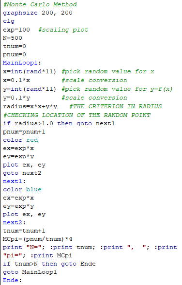
For example, all the webpages in this site are coded in HyperText Markup Language (HTML). Figure 13-03z19 is a very small segment taken from the page on "Monte Carlo Methods". It shows the enrichment of the text by linking to additional references, and a picture to attract attention. Beside adding more information, the presentation in the web is very important for advertiser to promote its products. There are HTML editor for free such as CoffeeCup. The HTML document can be uploaded to the Web Hosting Provider, which will manage the web browsing (for a fee). |
Figure 13-03z19 HTML as Markup Language [view large image] |
The source codes in Figure 13-03z19,a : "The Monte Carlo ....(Figure 01)". |


 ).
).


 File
File 


 )
)


