 |
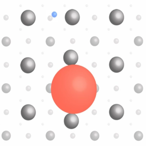
In the Higgs phase, the spin 1 Higgs bosons bound together to form something like the superfluid in the lowest energy state. Although we are not aware the existence of such directly, it is this condensate that endows mass to the elementary particles and ultimately our weight. The mass is generated via the interaction with this Higgs condensate as shown in Figure 13-05l. The top quark (red circle, the size is proportional to the interaction strength) is heavy because its coupling is large - the dragging manifests the effect as mass. The electron (blue circle) is much lighter, while the photon, which has zero mass, can move freely through the condensate. It seems that the Higgs condensate is only a mathematical odd-ball, since it is portrayed to be everywhere even at room temperature but we don't feel a thing about it. Its existence has been finally proven to be real on July 4, 2012 at LHC after spending US$ 4.5 billion just for building the machine alone. The Higgs boson with a mass of 125 Gev was detected by
|
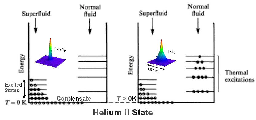

 0) ~ 13%. At finite temperatures, thermal excitations move more particles to the states in normal fluid (helium I). Superfluidity disappears beyond the lambda point (Figure 13-05d1). All those peculiar properties are related to the inert and coherent nature


 K similar to the formation of
  1, are imprinted to


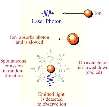
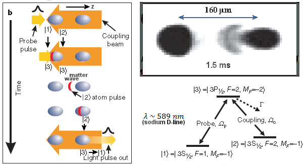
 v = p/m, where p = h/
 is the momentum of the photon, and m the mass of the atom. For D-line laser beam and sodium atom