

| Home Page | Overview | Site Map | Index | Appendix | Illustration | About | Contact | Update | FAQ |
|
|
The Josephson effect occurs in both bulk and 2-dimensional super-conductors when a piece of thin barrier (the junction) is inserted into the circuit. The weak link can be a thin insulating barrier (S-I-S) about 3 nm thick, a short section of non-superconducting metal (S-N-S) ~ 10 nm, or a physical constriction that weakens the superconductivity at the point of contact (S-s-S). The circuit consists of a biasing voltage V to control the current I flowing through the apparatus (Figure 13-08j). |
Figure 13-08j Josephson Junction, Circuit |
Figure 13-08k Josephson Junction, Mechanism [view large image] |

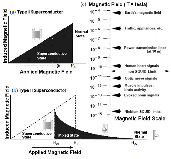 |
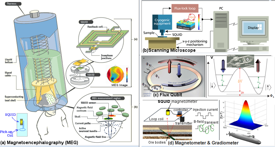
SQUID is a very sensitive instrument for measuring magnetic flux which is closely related to magnetic field. Figure 13-08l,c shows the range of measurable objects below and above the non-SQUID limit. It is made of two Josephson junctions on each side of a loop. The flux through the hole is detected via its relationship with the output current or voltage as shown in detail below. The superconductive materials can be either type I or type II (Figure 13-08l,a,b). Type I superconductors require very low temperature for the transition. It depends on the formation of Cooper pairs to attain the superconductive state (see list of Type I Critical Temperatures). The type II super-components are the vortices (see 2-D Superconductivity). The critical temperature for type II materials in 2-D is even lower. However, many compounds exhibit superconductive at much high Critical Temperature (see list of type II superconductors). |
Figure 13-08l SQUID |
 |
 |
The SQUID is a tiny equipment with a planar area of about 10-3m x 10-3m. It has to be kept inside a dewar with liquid helium (< 4.2K) or nitrogen (< 77K) to maintain the superconductive state (see Figure 13-08m,a for the basic components). It relies on the conversion of magnetic flux to voltage for performing the measurement. |
Figure 13-08m SQUID Flux-locked Loop |
Figure 13-08n SQUID, Operating Principle [view large image] |
See a detailed description of a commercial SQUID system (as shown in Figure 13-08m,a). |
 = h/p where p = mv + qA for the Cooper pairs in magnetic field B which is related to the vector potential A by the formula B = (
 X A).
X A). |
 |

|
Figure 13-08o Matter Wave [view large image] |
Figure 13-08p Stokes' Theorem |

 = 0) -
  1 = 2 ~
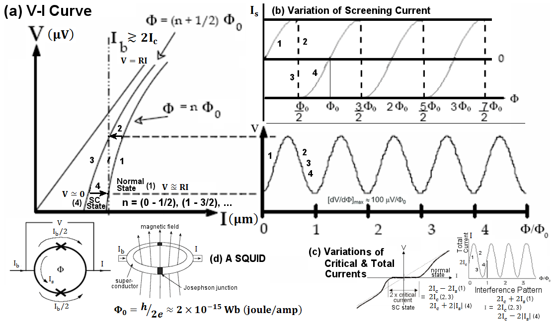
  /2.0 Flux where n = (0 - 1/2), (1 - 3/2), ... - 1 is to notice that Is has to be positive between /0 = 0 and 1/2. Then according to the formula to relate Is and /0, 1 + /0
  /2, or 1 /2 - /0. For example, 1 could be equal to /2 when /0 = 0; and it would become 0 when /0 = 1/2. Actually, it changes suddenly to negative at this point to 1 ~ -/2.2 (see formula) : 2 = 1 ~ /2 at /0 = 0; and 2 ~ (jump to /2) when /0 = 1/2 (see steps 1 and 2 of the constructive interference pattern in Figure 13-08n,c). 0 Flux where n = (0 - 1/2), (1 - 3/2), ... - 0, i.e., to allow the flux through the loop./0 = 1, 1 = 2 ~ /2, Is = 0, the cycle repeats anew (see formula, starting from n = 0, then 1, ...). In other words, the difference between 1 and 2 runs from 0 to and then back to 0 (see steps 3 and 4 of the destructive interference pattern in Figure 13-08n,c). .0 ~ 2x10-21 Wb. Since the magnetic field B = /S, where S ~ 10-6 m2 is the planar area of the SQUID, the minimum detectable magnetic field B ~ 10-15 T (T = tesla = 104 Gauss = Wb/m2 = joule/amp-m2). Figure 13-08l,c shows the range of magnetic field for various sources. The detectable limit is
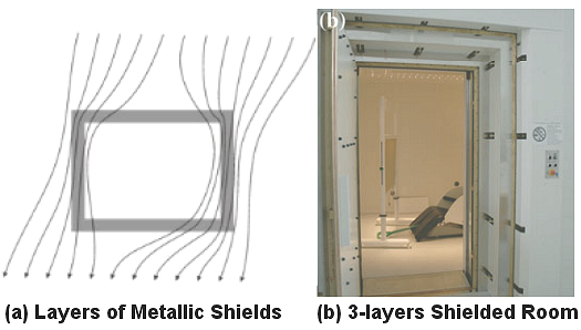 |
imposed by magnetic noise in the environment and the instrument itself, e.g, from muli-channels interference (by hundreds of SQUID within a device). The external sources can be minimized by metallic shielding (Figure 13-08q), while the contribution from the instrument can be reduced by signal processing software (see "Novel Noise Reduction Methods" for a review of the problem in Magnetoencephalography operation). In addition, the signal is very weak and cyclic, the output has to be amplified and integrated, this step is performed by the Flux-locked Loop as shown in Figure 13-08m,b. |
Figure 13-08q Magnetic Shielding [view large image] |
 |
|
Figure 13-08r SQUID Applications [view large image] |
In addition, SQUIDs are also used to check electrical activity in the stomach (Magnetogastrography, MGG), and in cardiology for magnetic field imaging (Magnetocardiography, MCG). |
 |
|
Figure 13-08s Flux Qubit |
with microwave frequency radiation which has an energy comparable to the gap energy  V. Figure 13-08s,b shows the state detection by another SQUID sensor. V. Figure 13-08s,b shows the state detection by another SQUID sensor. |
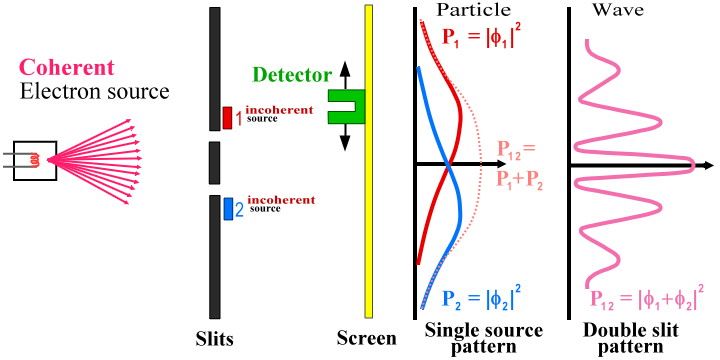 |
The full name of SQUID is Superconducting QUantum Interference Device. The interference is referred to the Cooper pairs emerging from the two Josephson junctions. Their quantum mechanical wave functions interfere with each other much like light waves from the double slits. The wave function's amplitude is proportional to the probability of the electron pairs, rather than to brightness as in the case of optical interference (Figure 13-08t). The pattern is the variation of the total current I as a function of /0 (see formula, and Figure 13-08n,c). |
Figure 13-08t Two Slits Optical Interference [view large image] |
![[view large image]](I13-07-shield.png)